

36V-84V 50A Sine Wave Brushless Controller | 500W-3000W


36V-84V 50A Sine Wave Brushless Controller | 500W-3000W
36V/48V/52V/60V/64V/72V/84V 50A Three-Mode Sine Wave Brushless Controller (500W–3000W
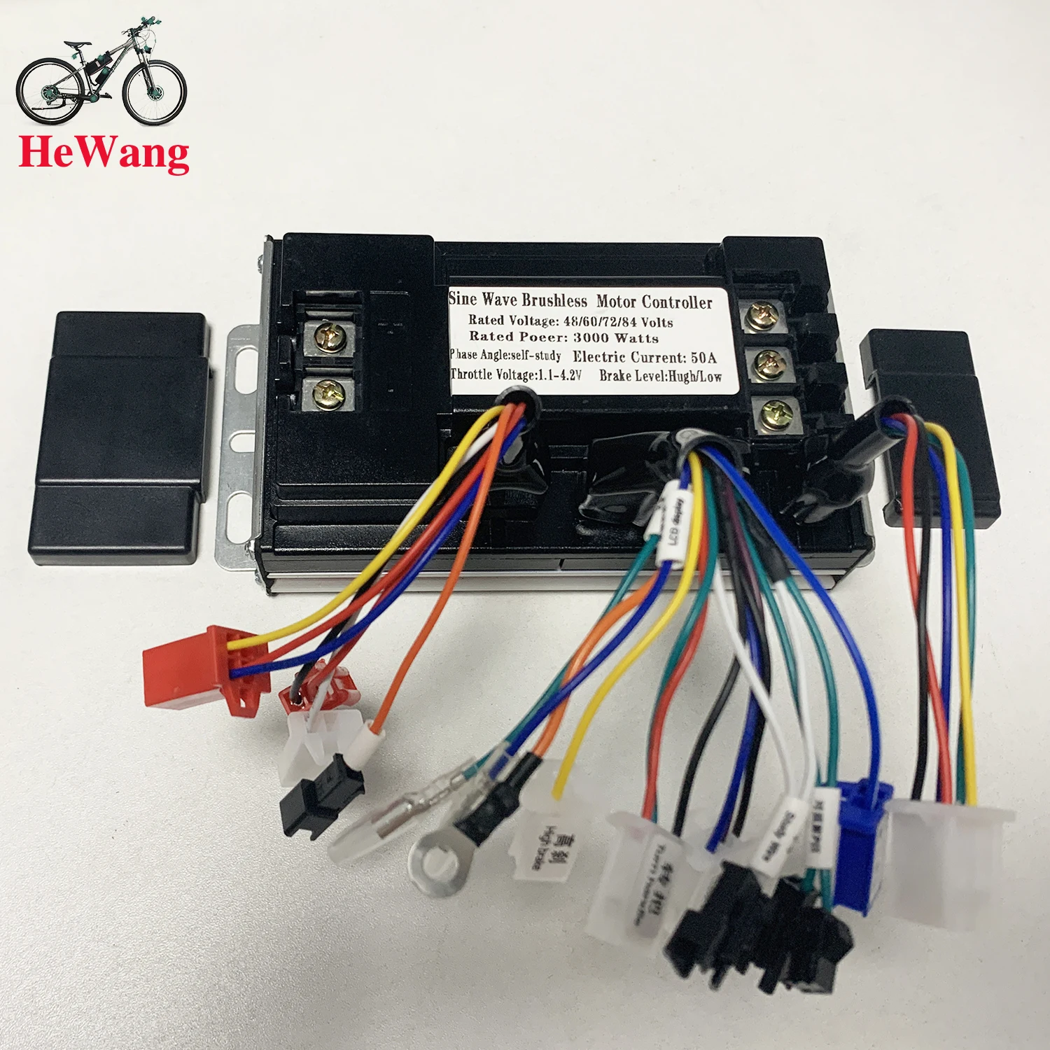
The 36V-84V 50A Three-Mode Sine Wave Brushless Controller handles high-power e-bikes and e-scooters with 50A continuous/peak current, SKST049N08 MOSFET power stages, and multi-voltage operation (36V up to 84V).
⚠️ System Compatibility & Voltage Range Guidelines
IMPORTANT SYSTEM INTEGRATION SPECIFICATIONS:
Wide Multi-Voltage Compatibility: Supports 36V, 48V, 52V, 60V, 64V, 72V, and 84V DC battery systems with automatic voltage detection.
Broad Motor Output Support: Engineered to drive 500W, 1500W, 2000W, 2500W, and 3000W 3-phase brushless DC hub or mid-drive motors.
Smart Three-Mode Operation: Automatically switches between Sine Wave (Hall-sensored), Square Wave, and Self-Study modes for reliable power delivery even if Hall sensors fail.
🚀 Key High-Performance Features
-
High-Power SKST049N08 MOSFET Stages: Upgraded heavy-duty power MOSFET transistors ensure low internal resistance, reduced operational heat, and high thermal efficiency under $50\text{A}$ loads.
-
Whisper-Quiet FOC Sine Wave Drive: Eliminates motor buzzing, shudder, and vibration during low-speed launches for smooth, linear acceleration.
-
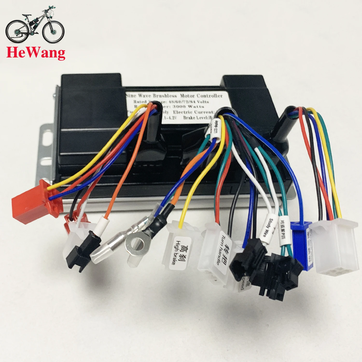
Rich Multi-Function Integration: Features pre-wired leads for 3-speed button shifting, anti-theft alarm signal/power, smart cruise control, high/low-level braking, and P-gear parking selector.
-
Dual Display Output Support: Supports direct wiring to both LCD smart instruments and traditional pointer/analog displays.
-
Compact Aluminum Alloy Heatsink: Robust $18\text{cm} \times 9.5\text{cm} \times 5\text{cm}$ sealed alloy casing for heat dissipation and weather resistance.
📊 Technical Specifications Matrix
| Specification Parameter | 50A Three-Mode Controller Specifications |
| Controller Architecture | Three-Mode FOC Sine Wave Brushless (BLDC) |
| MOSFET Specification | SKST049N08 Heavy-Duty MOS Tubes |
| Operating Voltage Range | 36V | 48V | 52V | 60V | 64V | 72V | 84V DC |
| Maximum Output Current | 50A Peak Current |
| Compatible Motor Power | 500W to 3000W Brushless Motors |
| Physical Dimensions ($L \times W \times H$) | $180 \times 95 \times 50\text{ mm}$ ($18 \times 9.5 \times 5\text{ cm}$) |
| Housing Material | Aluminium Alloy Weatherproof Heatsink |
| Core Functions | 3-Speed Shift, Anti-Theft Alarm, Cruise Control, High/Low Brake, P-Gear |
📋 Ideal Applications
The 36V–84V 50A Three-Mode Sine Wave Controller is engineered for:
-
500W to 3000W High-Output Electric Bikes, E-Scooters & E-Motorcycles
-
DIY High-Voltage Battery Upgrades (36V up to 84V Conversion Builds)
-
Replacement Drives for Off-Road Scooter & Moped Drivetrain Maintenance
📦 Package Contents
-
1 x 36V–84V 50A Three-Mode Sine Wave Brushless Motor Controller
-
1 x Self-Study Intelligent Recognition Calibration Wire Harness
-
1 x Wiring Harness Pinout Schema Diagram
Upgrade your high-power build with 50A three-mode sine wave performance! Select your options above, click Add to Cart, and order today!
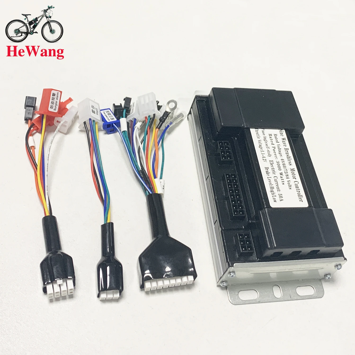
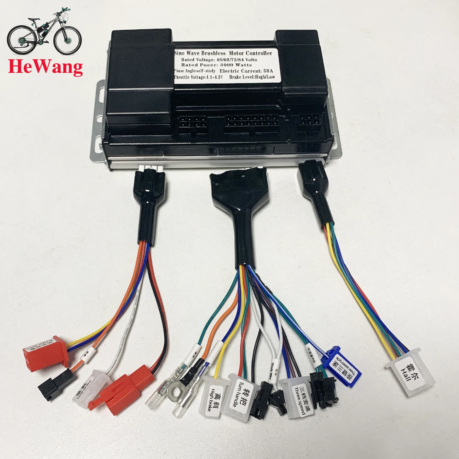 How to connect?
1. Connect the battery
2. connect the controller throttle line(color to color),connect electric lock
(If your throttle does not have a key lock, the controller key lock can be shorted)
3. connect the hall line(if motor without hall line, don't need connect)
4. Docking the two intelligent recognition lines, the wheel will move forward or reverse.
(11.If the wheel moves forward, separate the intelligent recognition line.
2.1 If the wheel reverses, separate the intelligent recognition line. Dock the intelligent recognition line again; if the wheel moves forward, separate the self-learning line.)
5. Other functions can be connected as needed.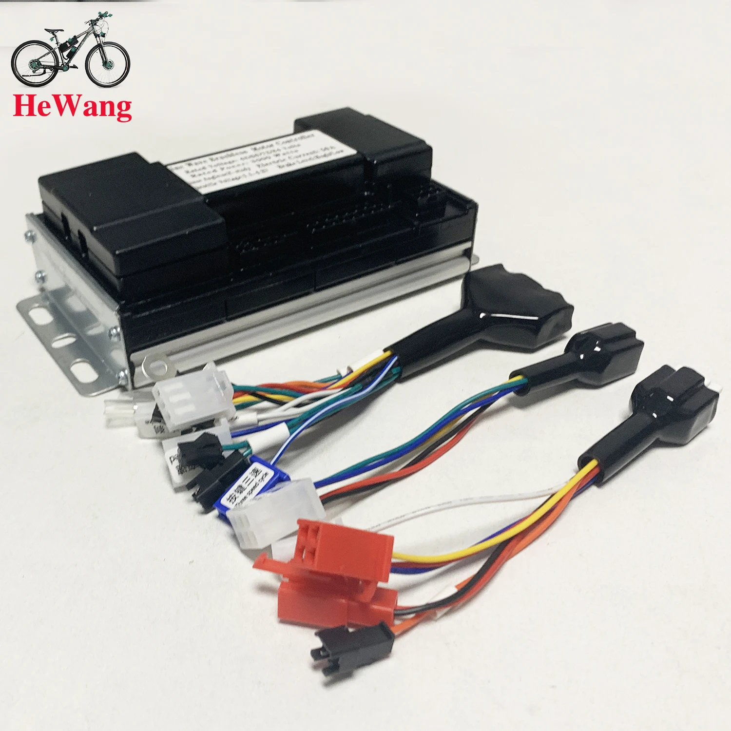
 1. Burglar alarm 2. Cruise 3. Low brake
4. Anti-theft power supply
5. Pointer instrument line
6. power cord 7. LCD display
8. High brake 9. Turn handle 10. study wire
11. Three speed 12.
P-file for plugging 13. Three-speed cycle
14. Hall 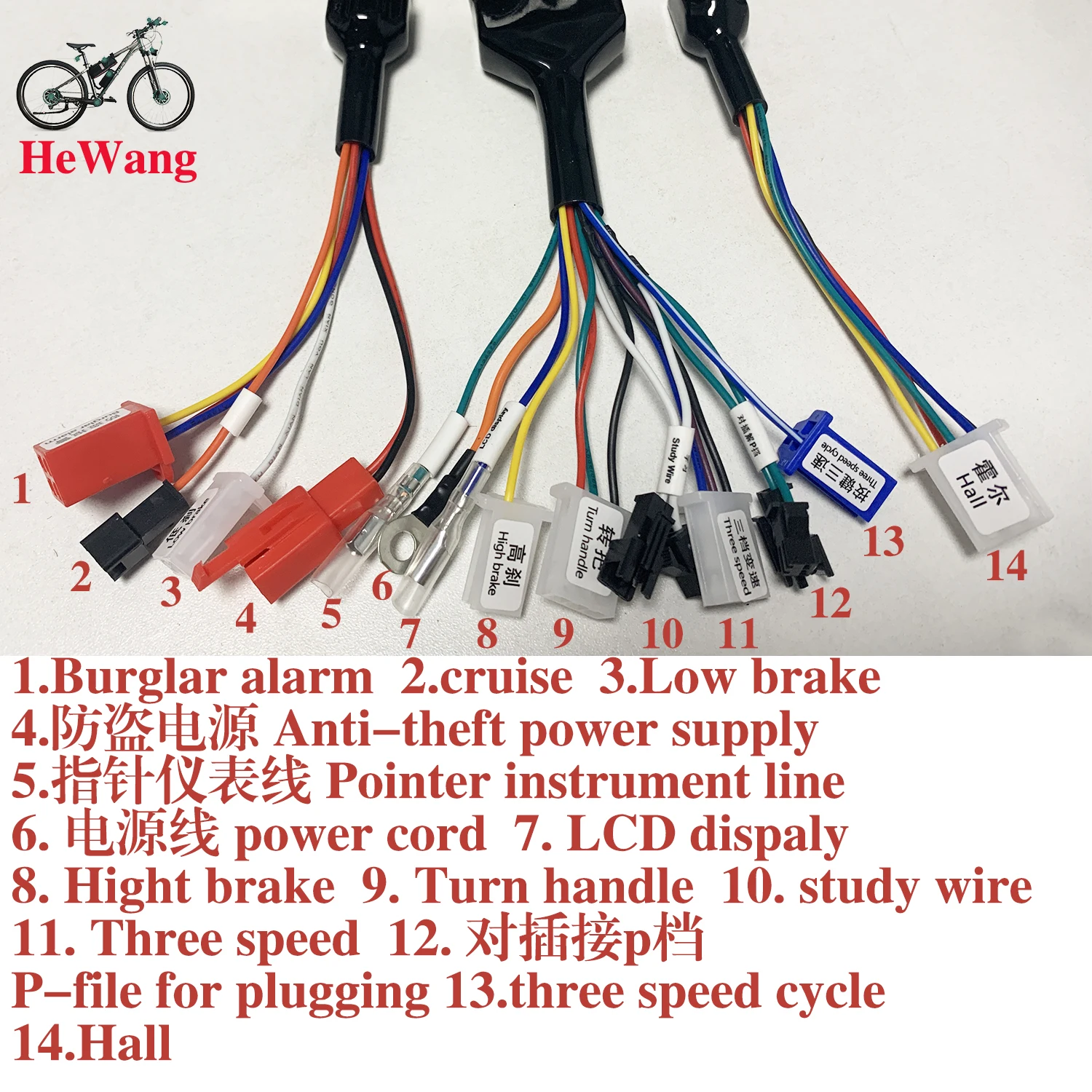
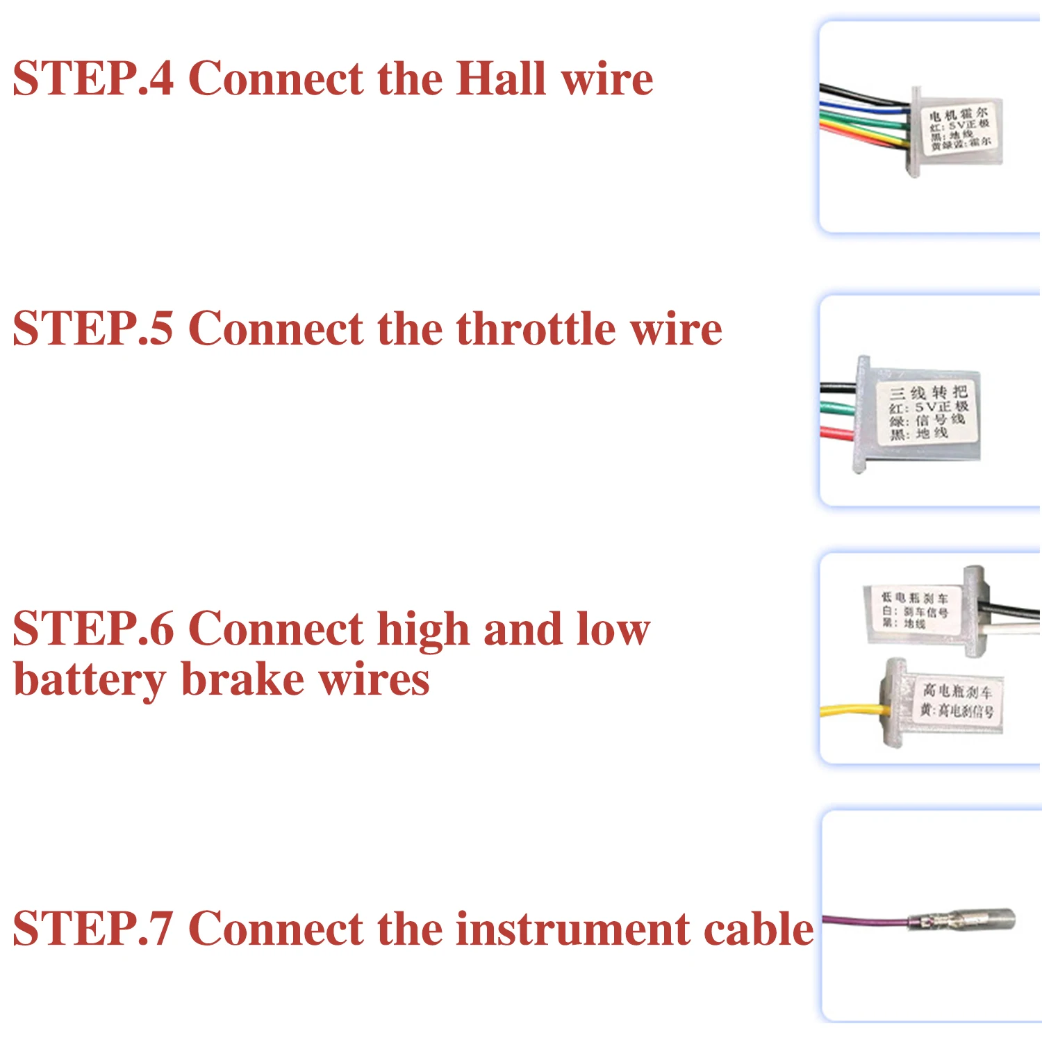
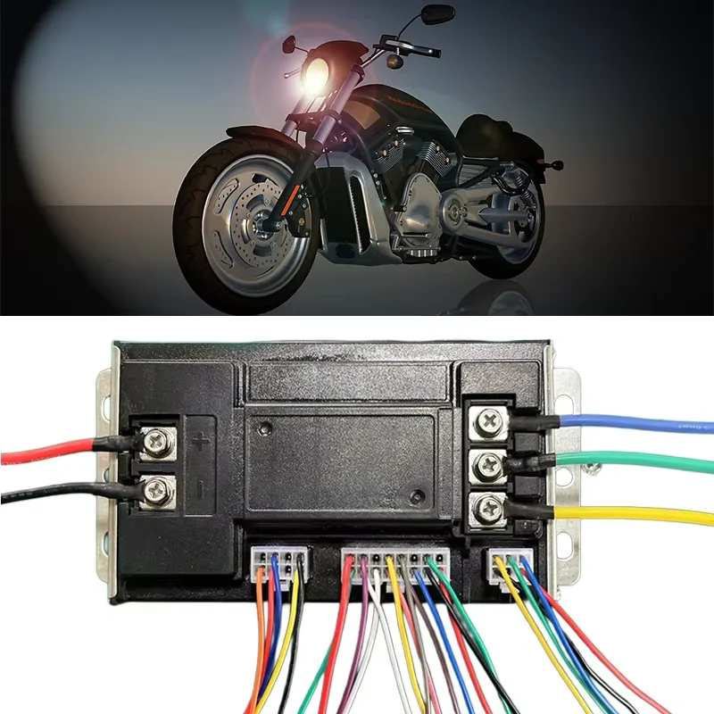 STEP.1 Connect the three wires of the motor first (the motor wires have no positive and negative poles, so you can connect them at will)
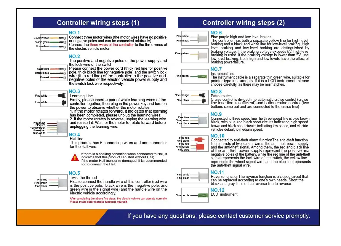
Connect the three thick yellow, green, and blue wires of the motor to the three motor wires of the electric car, and use the rear wheel to feel if there is any resistance. If there is no resistance, continue to the second step. If there is resistance, check whether the three wires of the motor are not connected properly. (How to detect whether the motor is good or bad: touch the motor wires of the car in pairs. If there is resistance, it means the motor is good. If there is no resistance, it means the motor has a problem).
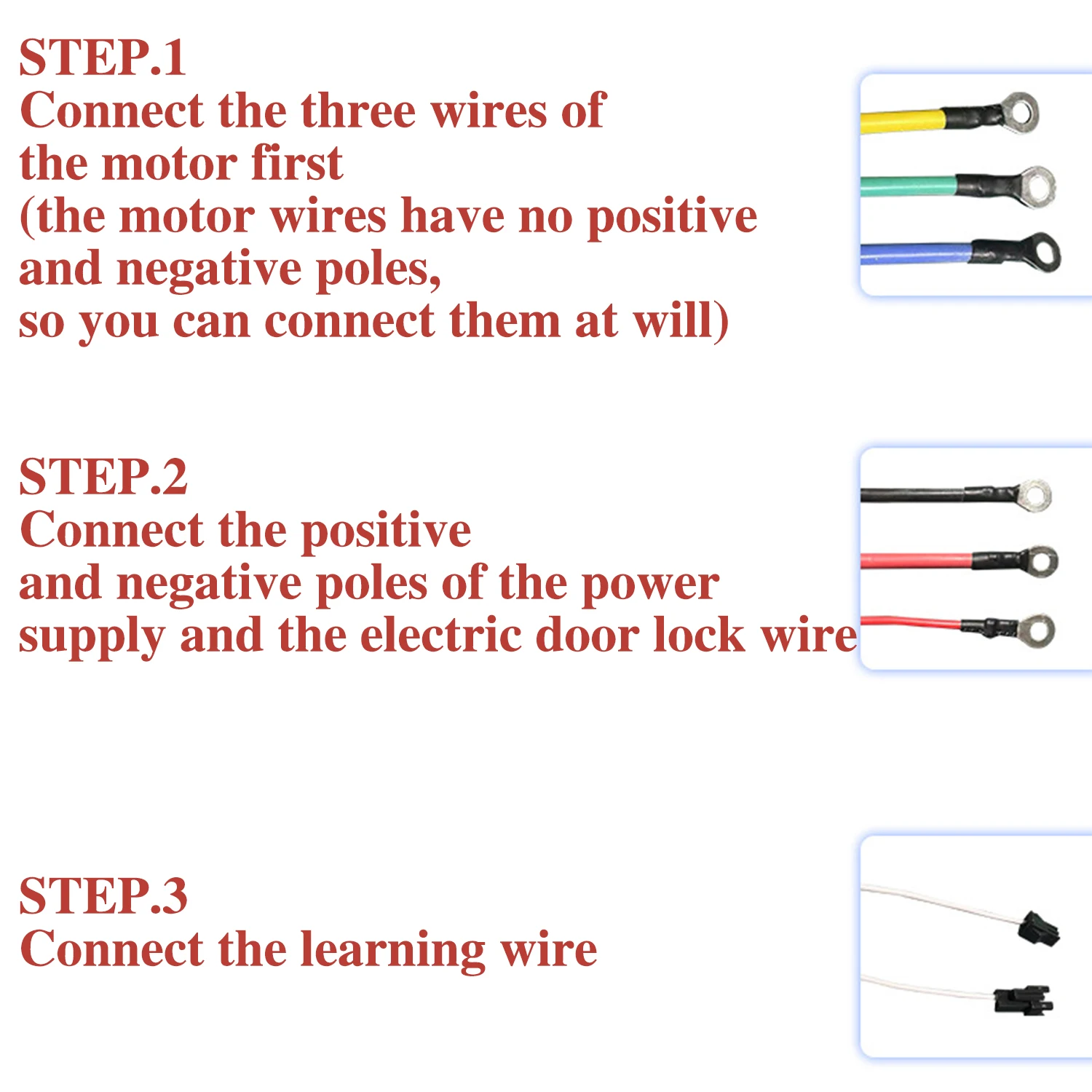
STEP 2: Connect the positive and negative poles of the power supply and the electric door lock wire
The power wire of the controller: the thick red is the positive pole, the thick black is the negative pole, and the thin red wire is the electric door lock wire, which can be matched with the positive and negative poles of the power supply and the electric door lock wire of your electric vehicle! (Note that the positive and negative poles of the power supply must not be connected in reverse; otherwise, the controller will be burned. If the electric vehicle does not have an electric door lock wire, the electric door lock wire on the controller and the positive pole of the power supply can be short-circuited together)
STEP 3. 3 Connect the learning wire
There is a pair of white learning wires on the controller. Plug the learning wires together, then plug in the power key, turn on the power, and see if the motor rotates automatically. If it rotates forward, just unplug the learning wire directly. If it rotates in reverse, unplug the learning wire and re-plug it to rotate forward, and then unplug the learning wire to complete the learning (after this step is completed, the motor automatically rotates to prove that the controller is good, and if it does not rotate, it proves that there is a problem with the controller)
 STEP 4. 4 Connect the Hall wire
Plug in the Hall wire, which has 5 wires with one head. Note: The Hall wire has positive and negative poles. The positive pole of the Hall wire of our controller is red, and the negative pole is black. As long as the positive and negative poles are correct, it doesn't matter if the other 3 wires have different colors. Our controller is a brushless controller, which can be used with or without Hall wires. However, if the Hall wire of the electric vehicle motor is broken, the following situations will occur: 1. The vehicle will shake and be weak when starting, but it will be fine when riding; 2. The anti-theft alarm can be used, but the motor lock function cannot be used; 3. The high gear of the three-speed cannot be used, but the low gear can be used
STEP 5. 5 Connect the throttle wire
Find the throttle wire for control: red, green, and black. Red is the positive pole of the throttle, black is the negative pole of the throttle, and green is the signal wire of the throttle. Then find the throttle wire on the electric vehicle; note that the throttle wire of the electric vehicle must come out of the throttle. If necessary, you can disassemble the throttle to identify which one is the throttle connector in the electric vehicle, connect the throttle connector, turn the throttle, and see if the motor rotates. If there is no response when turning the throttle at this time:
1. The positive and negative poles of the throttle are not connected correctly;
2. The throttle is broken; just change the throttle. (Friends with a multimeter can use the multimeter to test the throttle signal wire to see if there is a voltage output. Set the multimeter to the voltage output state, connect the red needle to the green signal wire of the throttle, and connect the black needle to the black ground wire of the throttle to see if there is a 0-5V voltage. If there is no voltage, it proves that the throttle is broken. Be sure to connect the controller and the throttle and turn on the power to test; otherwise, it will not work.
STEP 6. 6 Connect high and low battery brake wires
1. The controller has both a single yellow high battery brake wire and a white and black low battery brake wire. High battery brakes and low battery brakes are distinguished by brake voltage. If the brake voltage is higher than 5V, use the high battery brake, and if the brake voltage is lower than 5V, use the low battery brake. The effect of the high-battery and low-battery brakes is to cut off the power of the brake. First, identify how many wires come out of your brake handle: one for the high-battery brake and two for the low-battery brake. (If your car is a turn brake, you need to pull out the white and black low battery brake and put it together with the turn handle wire to achieve the effect of cutting off the power of the brake). 2. Because EABS electronic brakes are built into the controller program, the electronic brake effect will be generated as long as the brake power is cut off. The electronic brake is activated when the brake power is cut off. The motor generates a reverse force to brake. Sometimes there will be a "click" sound, which does not affect the motor. Please feel free to use it.
STEP 7. 7 Connect the instrument cable
The instrument cable is a single thin green cable, suitable for pointer instruments. If it is an LCD instrument, please choose carefully, as there may be mismatches.
STEP 8. 8 Connect the cruise line
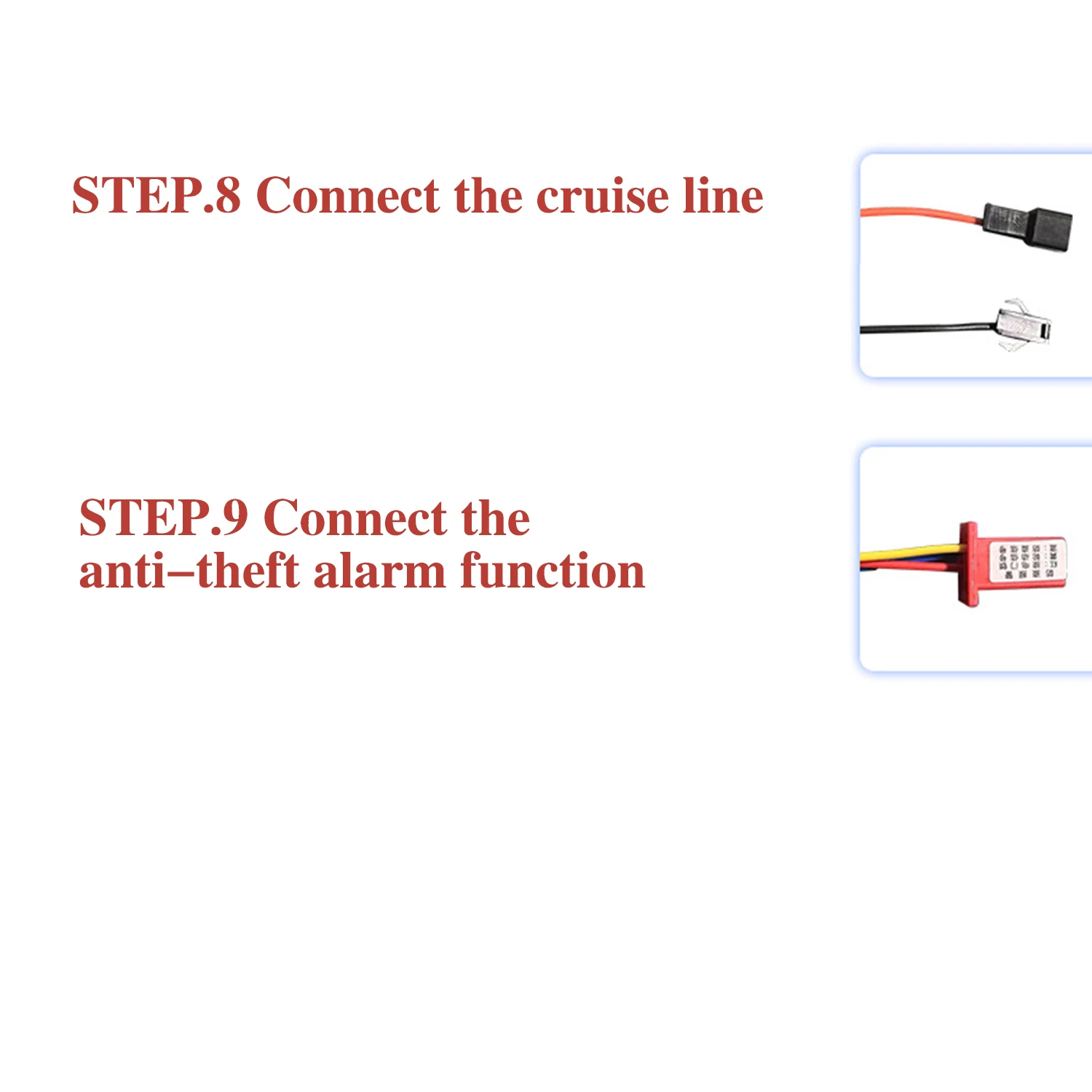
Cruise can be divided into automatic cruise (just plug in the cruise line) and button cruise (just connect the two lines from the button to the cruise line).
STEP.9 Connect the anti-theft alarm function
The anti-theft function line consists of two groups of lines: the anti-theft power supply and the anti-theft signal. Among them, the red and black lines of the anti-theft power supply represent the positive and negative poles of the battery, respectively, while the red line of the anti-theft signal is the electric door lock line, the yellow line is the wheel signal line, and the blue line is the anti-theft signal line. Be careful not to connect the different types of lines incorrectly!
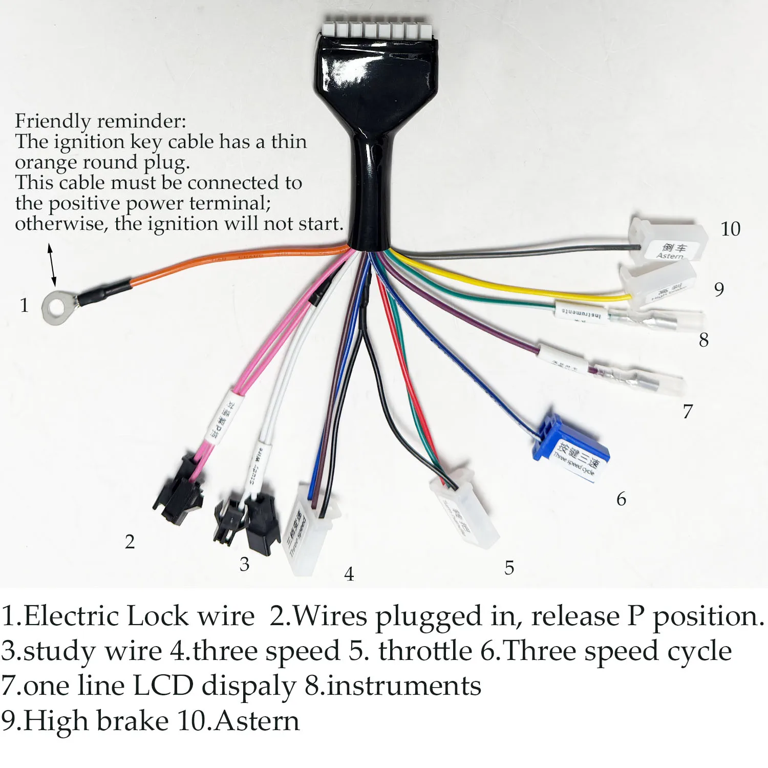 Friendly reminder: The ignition key cable has a thin orange round plug. This cable must be connected to the positive power terminal; otherwise, the ignition will not start.
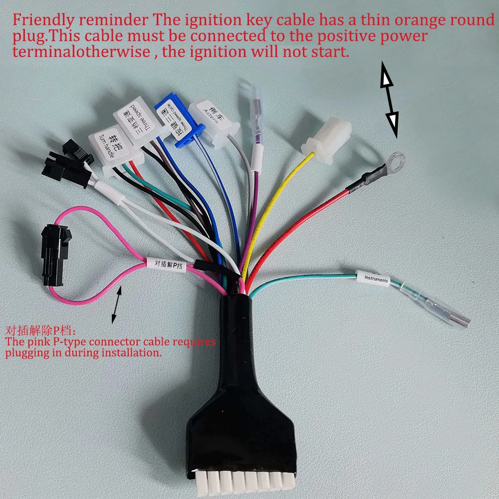 The pink P-type connector cable must be plugged in during installation.
Details
This product is crafted with quality materials to ensure durability and performance. Designed with your convenience in mind, it seamlessly fits into your everyday life.
Shipping & Returns
We strive to process and ship all orders in a timely manner, working diligently to ensure that your items are on their way to you as soon as possible.
We are committed to ensuring a positive shopping experience for all our customers. If for any reason you wish to return an item, we invite you to reach out to our team for assistance, and we will evaluate every return request with care and consideration.


